
A metre of solid glass, 50 mm across, contains enough material for about 160 km of bare fibre 125 micrometres in diameter. The arithmetic is a useful way to picture a draw tower. The preform is 400 times wider than the strand. Its cross-sectional area is therefore 160,000 times as large. That is an idealised calculation for a uniform cylinder, before the unusable ends and rejected lengths are removed. It also explains why a flaw in a short piece of preform can matter a long way down the finished spool.
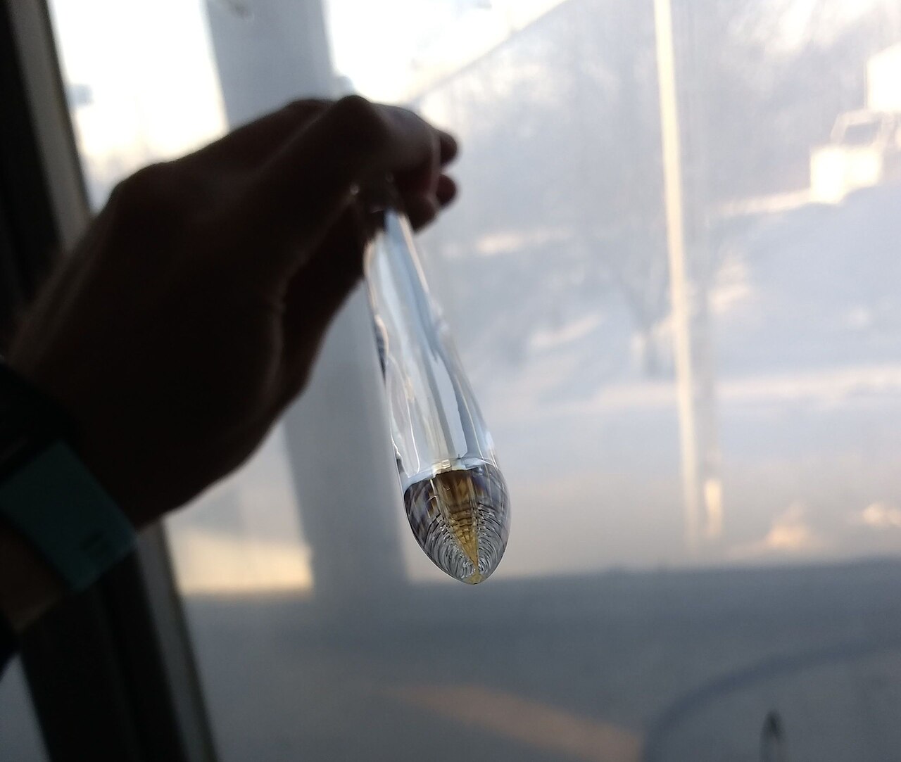

Building the path that light will follow
Follow a preform made by outside vapour deposition (OVD), one of several routes to optical fibre. A burner moves along a rotating rod, depositing fine glass particles in successive layers. Fibre makers call this deposit “soot”. The name describes its powdery texture. It looks chalky white because light scatters at the countless boundaries between the particles and the gas in the pores. Corning’s account of the OVD process.
The glassmaker can change the composition as the layers build up. In a common design, germanium tetrachloride (GeCl₄) supplies germanium for the core. The resulting germanium dioxide raises the refractive index of the silica there. Once the core is surrounded by glass of slightly lower index, light can be guided along it. Drawing stretches that pattern out over the full length of the fibre. Other processes deposit material on the inside of a glass tube. The choice of preform route determines where the gases and chemical precursors enter the plant. Corning on germanium in optical preforms.
Why use helium around a piece of glass?
The loose structure gives the glassmaker a brief opportunity. While the pores still connect to one another, a drying gas can reach deep into the deposit. In a chlorine-based process, that treatment reduces hydroxyl groups, chemical bonds that would absorb part of the light sent through the finished fibre. Next, heat fuses the particles. The preform shrinks and turns transparent as the boundaries between particles disappear. Preform drying and consolidation.
The last pockets of gas present a different problem. As each pore closes, the route back out through neighbouring pores vanishes. Helium can dissolve in and diffuse through hot silica, which helps these pockets disappear. A less permeable gas can leave bubbles that stretch into elongated voids when the fibre is drawn. The chemistry of drying and the escape of trapped gas both affect the final glass, for different physical reasons. Corning on gas permeability during consolidation.
Engineers at Prysmian tested how much the furnace itself matters. They changed the seal and gas flow around the moving rod that holds the preform. They added up the lengths of defective sections shorter than 18 metres, identified by diameter measurements during the draw, and divided that sum by the total length drawn. The modified furnace achieved a result below 1% at a helium flow of 30 standard litres per minute. The comparison furnace reached that threshold at 40. A flow setting copied from one machine to another would have missed the effect of air entering around the rod. Prysmian’s furnace comparison, Example 1 and Table 1.
Fifty milliseconds to cool the glass
The consolidated preform next enters the draw furnace. Its tip softens, narrows and feeds a continuous strand. Equipment below the furnace controls the draw speed and diameter. A coating die further down the tower surrounds the bare glass with liquid polymer, which is then cured to protect its surface. The strand must reach the die cool enough for the coating to flow evenly around it. In a helium cooler, gas flows around the moving strand. Helium conducts heat more readily than air, so it helps carry heat away from the glass during the short journey to the die. Cooling and coating on a draw tower.
Consider an illustrative one-metre cooling section. At 20 metres per second each point on the glass travels through it in 50 milliseconds. At 40 metres per second it has just 25 milliseconds. The moving strand also drags a thin layer of air into the cooler. In Kyoungjin Kim’s computer simulations, extra helium initially displaced some of that air and improved cooling. Beyond a certain flow, adding more gas gave no further improvement in the model. The direction of flow mattered too. To assess a speed increase, an engineer therefore needs the temperature of the glass arriving at the coating die as well as the reading on the helium meter. Kim’s draw-tower cooling study.
What a production shift can tell the buyer
At the consolidation furnace, record fresh helium per accepted preform of a given size and design. At the tower, divide fresh helium by kilometres of fibre that pass inspection at the target speed. If the cooler circulates recovered gas, measure fresh make-up separately. For example, a shift that uses 24 normal cubic metres of fresh helium and releases 600 km of fibre has used 40 normal litres per accepted kilometre. Over the next shift the meter might show the same 24 cubic metres, yet if only 480 km pass, consumption rises to 50 litres per accepted kilometre. The production records explain a change that the gas meter alone would hide. Air Products on draw-tower gas recovery.
Those measurements help size a supply. A buyer can give the supplier the normal and peak flows, required inlet pressure, limits on individual impurities and how long the line must operate between deliveries. Gas volumes need a stated reference temperature and absolute pressure. If the site receives liquid helium and vaporises it, keep the liquid litres delivered separate from the gas volume metered at the tower.
Request a helium supply quotation
Also in Insights · Why optical fibre makers use deuterium after drawing.